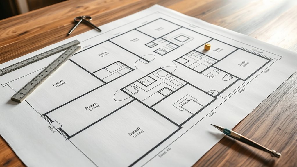
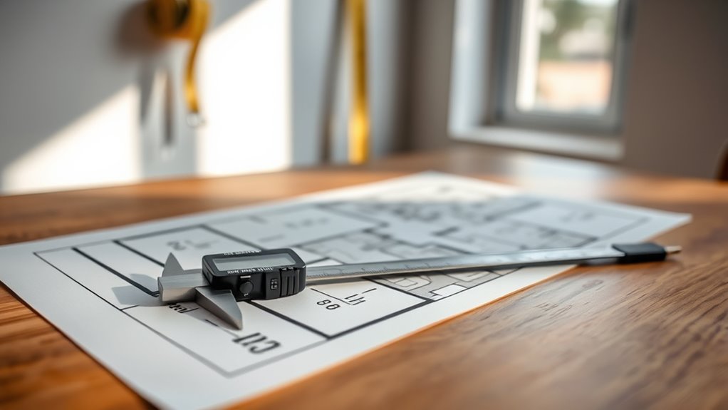
To read floor plan measurements, start by understanding the scale ratio to convert paper dimensions into real-world sizes. Identify symbols for walls, doors, and windows, noting their dimensions and placement. Measure wall lengths and room sizes as labeled, paying attention to wall thickness and whether dimensions are from center-to-center or face-to-face. Decode door swings and window notations for accurate spatial orientation. Recognize furniture layouts to assess space flow and usability. As you explore further, additional steps will clarify how to cross-reference plans for precision.
Understanding the Basics of Floor Plans

Before you can accurately interpret floor plan measurements, you need to understand the fundamental components that make up a floor plan. Floor plan basics include the scaled, two-dimensional representation of a building’s architectural layouts, showing walls, doors, windows, and fixed installations from a top-down perspective. You’ll notice that each line and shape corresponds directly to physical elements, with dimensions usually marked in feet and inches or metric units. Recognizing the proportional relationships between spaces empowers you to grasp room sizes, circulation paths, and spatial organization. Understanding these core elements liberates you to confidently analyze and visualize the built environment, ensuring you can make informed decisions without relying solely on verbal descriptions or photographs. Mastering this foundation is essential before moving to more complex aspects of floor plan interpretation.
Identifying Common Symbols and Icons
Once you grasp the basic layout and dimensions on a floor plan, the next step is to recognize the standardized symbols and icons that represent various architectural elements. These common icons and measurement symbols serve as a universal code, allowing you to interpret the plan with precision and confidence. Understanding them grants you the freedom to visualize spaces accurately without ambiguity.
| Symbol | Meaning |
|---|---|
| Door (arc) | Entry/exit point |
| Window (rectangle) | Natural light access |
| Wall (thick line) | Structural boundary |
| Stairs (zigzag) | Vertical movement |
| Fixture (circle) | Plumbing or electrical |
Mastering these symbols guarantees you read floor plans fluently, providing the freedom to design, modify, or evaluate spaces effectively.
Interpreting Measurement Units and Scales

Understanding the measurement units and scales used in floor plans is vital for accurate interpretation and application. Floor plans typically use scale ratios to represent large spaces on manageable paper sizes. You’ll often encounter scales like 1:50 or 1/4”=1’, indicating that one unit on the plan corresponds to 50 units or one-quarter inch to one foot in reality. Mastering measurement conversions between imperial and metric units is essential, especially if the plan doesn’t specify the system used. To guarantee precision, always verify the scale ratio before translating dimensions into real-world sizes. This approach frees you from miscalculations, allowing you to confidently gauge spatial relationships and dimensions without ambiguity or error. Accurate interpretation hinges on your ability to seamlessly convert and apply these scales.
Reading Wall Dimensions and Room Sizes
You’ll start by examining wall lengths, which are usually marked along the exterior and interior edges with exact measurements. Next, focus on room dimensions typically indicated by width and length, ensuring you note the units and scale used. Accurately interpreting these details allows you to visualize actual space sizes and spatial relationships on the plan.
Understanding Wall Lengths
Wall lengths in floor plans are typically represented by numerical values adjacent to the corresponding lines, indicating the distance between structural points in feet and inches or metric units. When interpreting these measurements, you must account for wall thickness, as it influences the overall space and affects installation or renovation plans. Measurement accuracy is vital; inaccuracies can lead to costly errors in material ordering or spatial layout. Usually, exterior walls are thicker than interior walls, and plans may specify this with different line weights or annotations. To guarantee you’re reading lengths correctly, verify if dimensions are center-to-center or face-to-face of the walls. Paying close attention to these details grants you the freedom to visualize and manipulate spaces confidently and precisely.
Decoding Room Dimensions
Although room dimensions might seem straightforward, accurately interpreting them requires attention to how lengths are presented and what they specifically refer to. When you decode room dimensions, focus on how measurements define the room layout and impact space utilization. Remember:
- Dimensions usually indicate clear wall-to-wall distances, excluding wall thickness.
- Verify if measurements include built-in features like closets or niches.
- Understand that irregular shapes may list multiple segments to define total room size.
- Note dimension lines parallel to walls; they reveal the usable floor area.
Interpreting Scale and Units
After understanding how room dimensions define usable space, the next step is to interpret the scale and units used on floor plans accurately. Floor plans typically use a specific scale ratio—like 1:50 or 1/4″=1’—which requires precise scale conversion to translate plan measurements into real-world dimensions. You must verify the unit system, whether metric or imperial, to guarantee measurement accuracy. Walls, doors, and windows are marked with dimensions that reflect their true size once scaled. Employing a ruler or digital tool calibrated to the plan’s scale helps convert lengths correctly. By mastering scale conversion and unit interpretation, you gain freedom to plan effectively, avoiding costly errors in construction or furnishing. Accurate reading of wall dimensions and room sizes ultimately empowers confident spatial decisions.
Decoding Door and Window Annotations
You’ll notice door symbols usually include an arc indicating the swing direction and size, which helps you determine clearance and placement. Window annotations often specify width and height in feet and inches, essential for understanding natural light and ventilation. Mastering these symbols guarantees you accurately interpret openings within the floor plan.
Understanding Door Symbols
Door symbols on floor plans provide essential information about the type, size, and swing direction of each door, enabling you to visualize how spaces connect and function. To accurately interpret these symbols, focus on key aspects like door types and door placement. Each symbol typically shows:
- The door leaf as an arc illustrating the swing path and direction.
- The door frame as a solid or dashed line indicating structural boundaries.
- Specific door types, such as hinged, sliding, or double doors, represented by distinct symbols.
- Placement relative to walls, helping you assess clearance and traffic flow.
Interpreting Window Dimensions
Just as door symbols convey specifics about type and movement, window annotations provide detailed measurements that define size, placement, and function within a floor plan. When interpreting these dimensions, focus on the width and height values, typically given in feet and inches or metric units, ensuring measurement accuracy for precise installation. Different window types—such as casement, sliding, or fixed—are indicated by unique symbols or abbreviations, clarifying their operational style. Placement is often shown relative to adjacent walls or floors, helping you visualize natural light and ventilation flow. By decoding these annotations, you gain full control over spatial planning and aesthetic decisions, avoiding costly errors. Understanding window dimensions lets you confidently customize your environment while respecting architectural intent and structural constraints.
Recognizing Furniture and Fixture Layouts

Several key elements help you identify furniture and fixture layouts on floor plans, including standardized symbols, scale dimensions, and spatial relationships. When examining the plan, focus on how furniture placement aligns with room function and flow. Fixture types like sinks, toilets, and lighting are represented by consistent icons that differentiate them from movable furnishings. To effectively recognize these layouts, consider:
Identify furniture layouts by focusing on standardized symbols, scale, spatial relationships, and alignment with room function.
- Symbol shapes and labels indicating fixture types
- Scale measurements ensuring accurate furniture size
- Proximity of furniture to walls and openings
- Orientation reflecting intended use and accessibility
Using Floor Plans to Estimate Space and Flow
A clear understanding of a floor plan’s spatial layout is essential when estimating how effectively space will function in real life. You’ll begin by measuring room dimensions and noting furniture placement to assess space utilization accurately. Flow analysis comes next—you’ll track pathways between areas, ensuring movement isn’t obstructed. Look for logical connections, such as access between living spaces and amenities, which support natural circulation. Pay attention to door swings and window placements, as these impact usability and flow. By interpreting these elements, you can predict whether the design accommodates your lifestyle needs without feeling cramped or disjointed. Mastering this lets you evaluate how a floor plan balances openness with functional zones, granting you freedom to envision living comfortably within the given spatial constraints.
Tips for Cross-Referencing With Other Architectural Drawings
Accurately estimating space and flow from a floor plan often requires verifying measurements and details against other architectural drawings. When you’re cross referencing elevations, you gain a vertical dimension perspective that confirms wall heights and window placements. Comparing site plans helps guarantee the building footprint aligns with property boundaries and landscape features. To maintain accuracy, focus on these key actions:
Cross-referencing elevations and site plans ensures precise measurement and alignment of architectural elements.
- Verify room dimensions on floor plans against elevation heights
- Cross check door and window sizes between plans and elevations
- Align site plan setbacks with floor plan perimeters
- Confirm utility placements on floor plans match site plan details


